Jk Latch In Verilog Code


Jk Latch In Verilog Codes
At the NAND gate, flip-flop construction is very simple with two NAND gates. One of the inputs is S’ which goes to the first input of a NAND gate. The other input R’ is in conjunction with the other NAND gate. The output of the gate associated with the R input has output Q’ which also acts as the input of the first NAND gate. Thus now the first NAND gate has two inputs, namely S’ and Q’n+1.
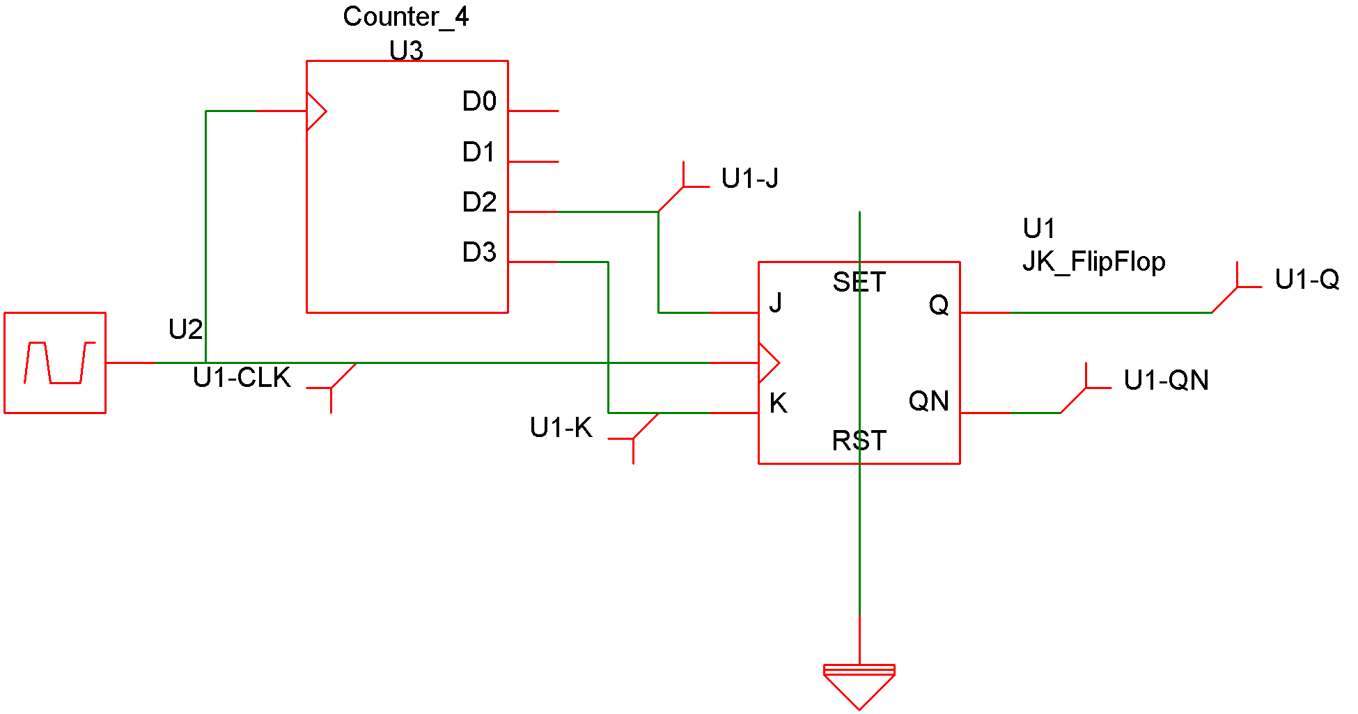
- Nov 25, 2015 Hi was trying to write Both structural and Test bench code for D-flip flop using JK flip flop as well as JK-Flip flop using SR flip flop. But i was getting the some errors. Please anyone could help me out thanks in advance. Here is my Coding. Structural for D2jk.
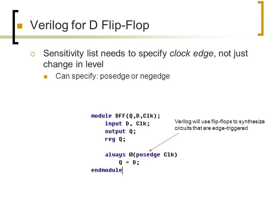
- Learn about the design of D-latch in verilog code with example and the testbench to verify its functionality D Latch A flip-flop captures data at its input at the positive or negative edge of a clock.

Latches can also be modeled in Verilog, either by a structural model based on gates or behaviorally as we do in the following with flip-flops. However, the use of latches is typically avoided when synthesizing Verilog for an FPGA as the timing is difficult to analyze. Modeling Flip-flops.
Jk Flip Flop Pin Diagram
In similar fashion, the other hand gate also has two inputs, namely R’ and Qn+1. Here Qn+1 and Q’n+1 act as the feedback to NAND gates and thus they are able to store one bit. This formation of NAND gates is also called bi-stable latch.